

2003+ GM Express/Savana Vans and Isuzu NPR/NQR Crank Drill Procedure
It is important before starting this or any other procedure, that you or anyone who operates, works with, maintains, services or repairs the Butler System and/or vehicle, be familiar with its operation and thoroughly read, understand and follow, in their entirety, all of the Warnings, Cautions, and Notices described in your Butler System and vehicle Owners’ Manuals.
Carefully read and understand the complete list of instructions before proceeding.
Procedure: To drill three precisely located holes in the front face of the engine’s crankshaft and install the Butler System Crankshaft Adapter to the front face of the engine’s crankshaft.
Applicable Models: 2003+ GMC/Chevy 4.8l, 6.0l, and 6.6l V8 Gas engines installed in Express/Savana vans, Express/Savana cut-away chassis and Isuzu NPR/NQR cab-over trucks.
Who Should Perform This Procedure: This procedure is to be performed only by qualified service technicians who possess the knowledge, skill, tools, hardware, and/or equipment required to perform this procedure. It should not be attempted by persons who do not have significant automotive mechanic skills or experience.
IMPORTANT: Use only a Butler System Crank Pulley with a YELLOW label. Pulleys identified with a YELLOW label are adjustable and require the following procedure to complete the proper installation. Failure to properly adjust (align) the pulley may result in engine vibration and possible damage to the vehicle and/or Butler System.
Special Tools Provided by The Butler Corporation: (shown below)
- Drill depth gauge
- 3/16" drill bits (2)
- Crank jig & bolt
- Alignment gauge
- Kent-Moore tool J-42386-A flywheel lock
- Chamfering bit
- Crank adapter guide bolt
- ½" Drive 14mm hex socket
Special Tools: (continued)
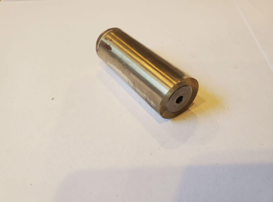
Drill Depth Guide
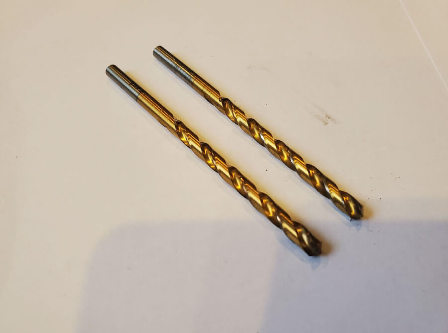
3/16" Drill Bits
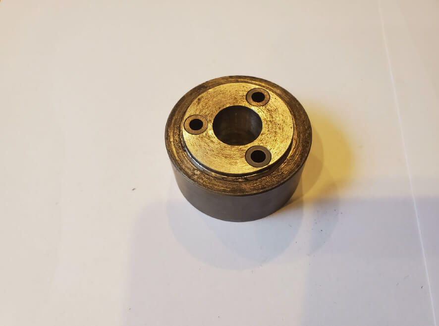
Crank Drill Jig
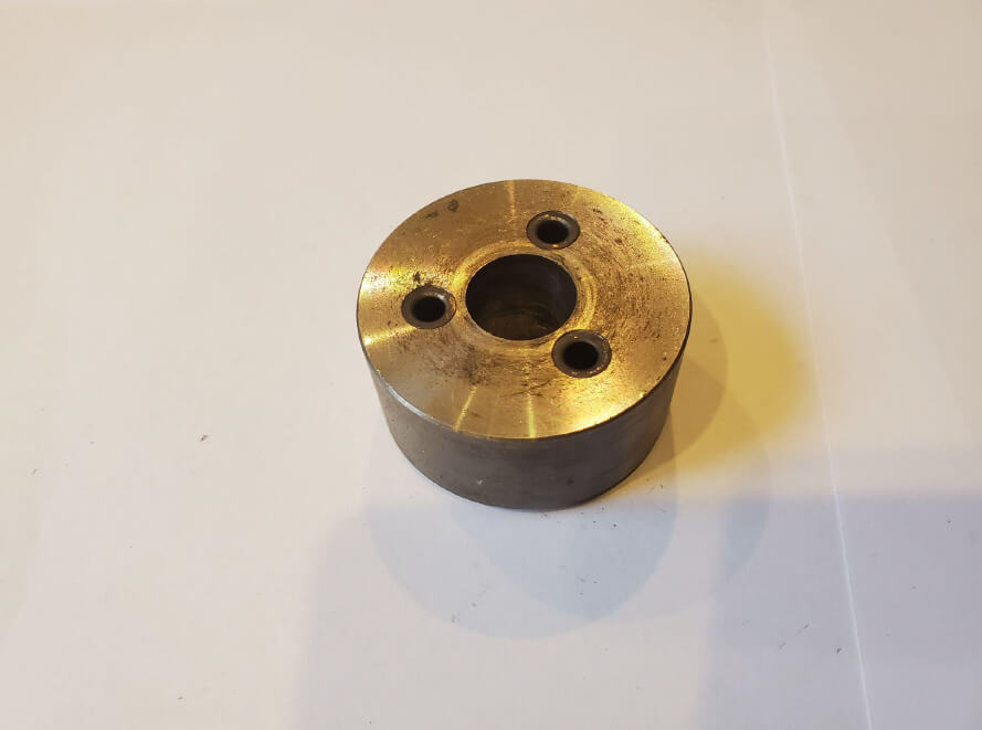
Crank Drill Jig
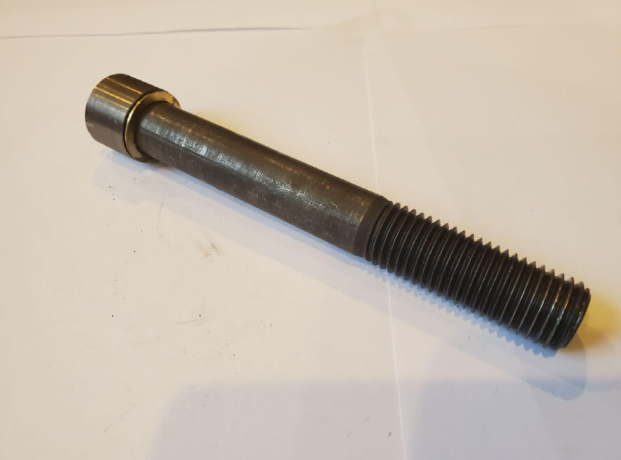
Crank Drill Jig Bolt
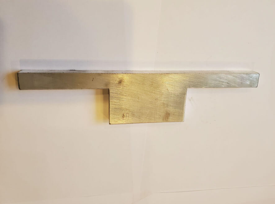
Alignment Gauge
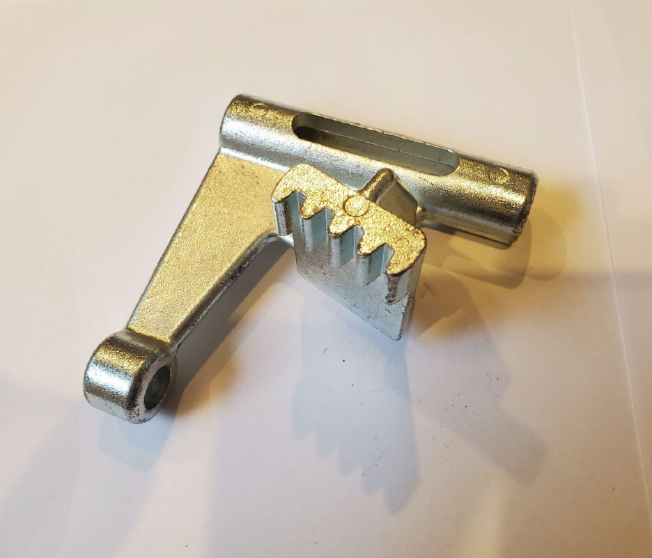
Kent-Moore tool J-42386-A flywheel lock
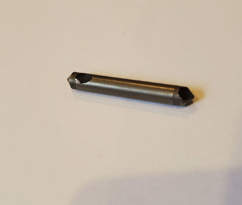
Chamfering bit
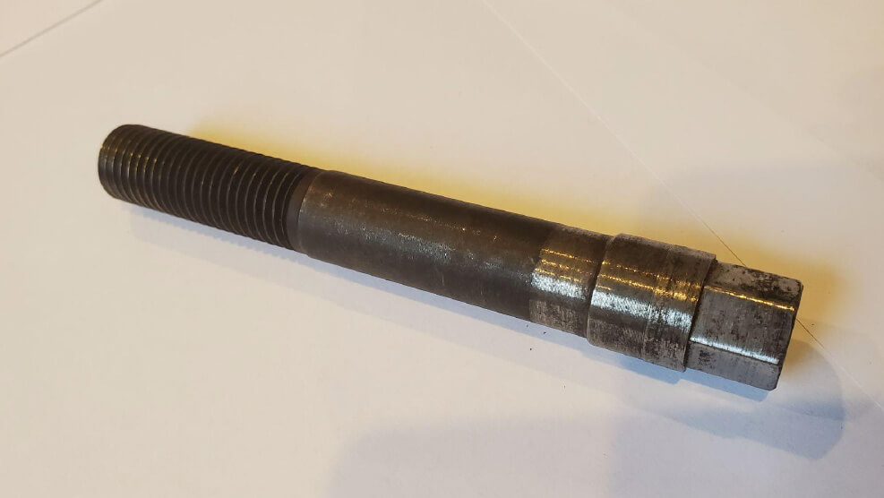
Crank Guide Bolt
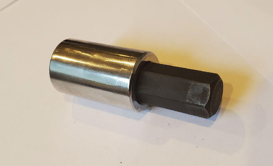
Hex Socket
Components to be Installed: (shown below)
- Crank Bolt (with thread sealant applied)
- Butler System Crank Pulley Adapter (model year dependent)
- Butler System Crank Pulley (must have yellow label)
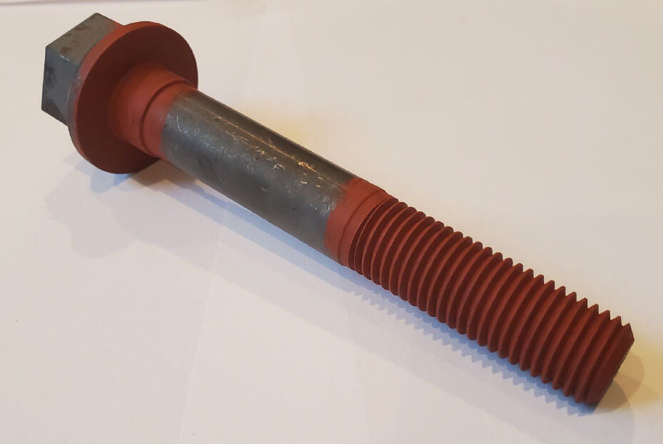
Crank Bolt
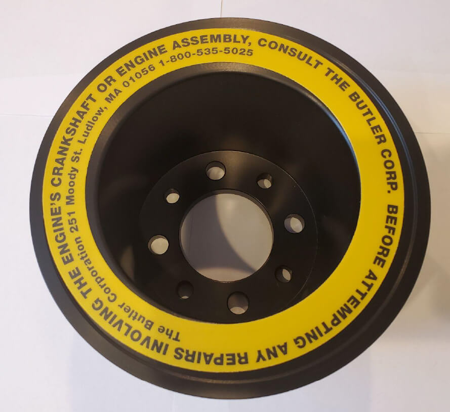
Butler System Crank Pulley
CAUTION: The crank bolt is a Butler Corporation supplied component and is a torque-to-yield fastener and can only be tightened to final torque one time. The crank bolt MUST BE REPLACED any time it is removed. Failure to do so may result in damage to the Butler System and/or vehicle.
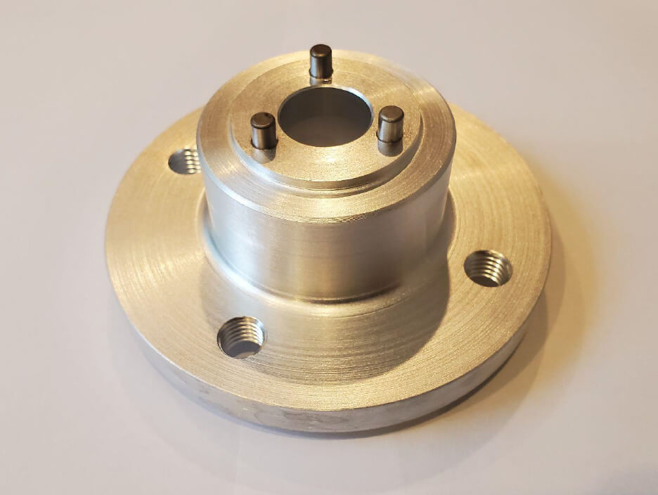
2003-2020 4.8L & 6.0L Butler System Crank Pulley Adapter
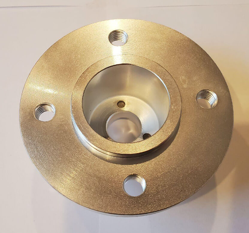
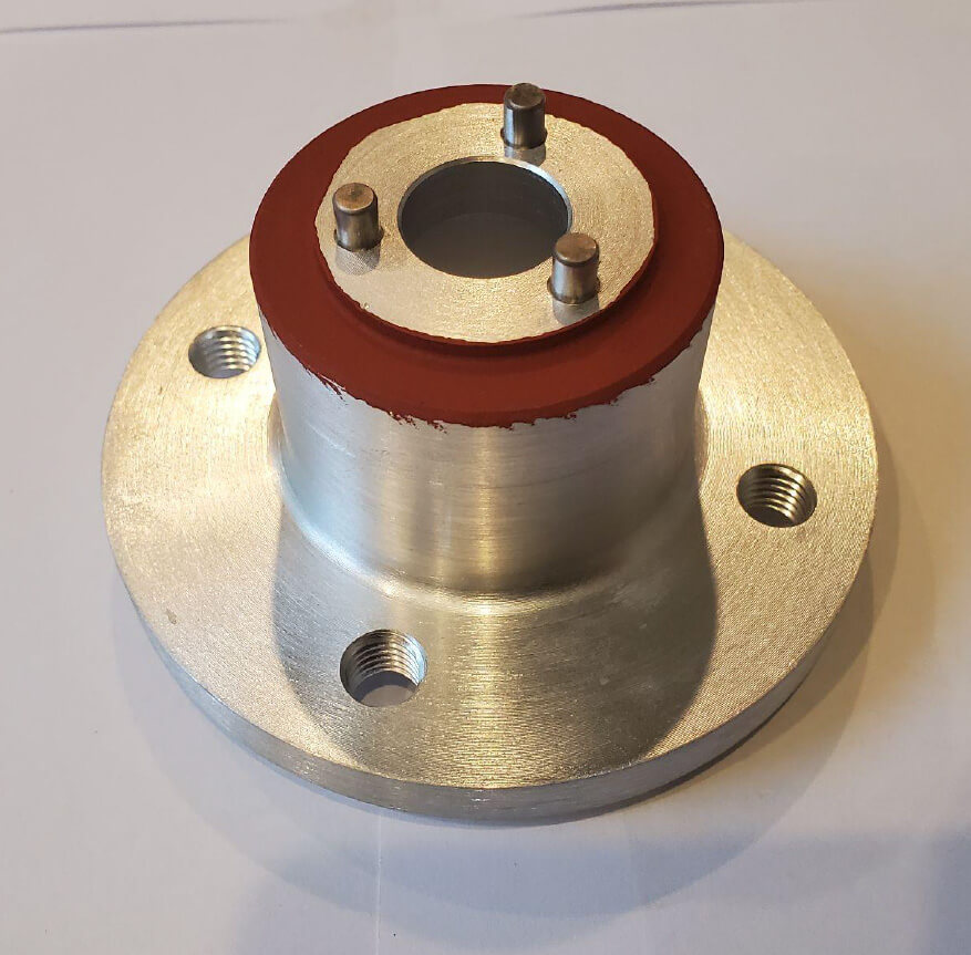
2021 + 6.6L Butler System Crank Pulley Adapter
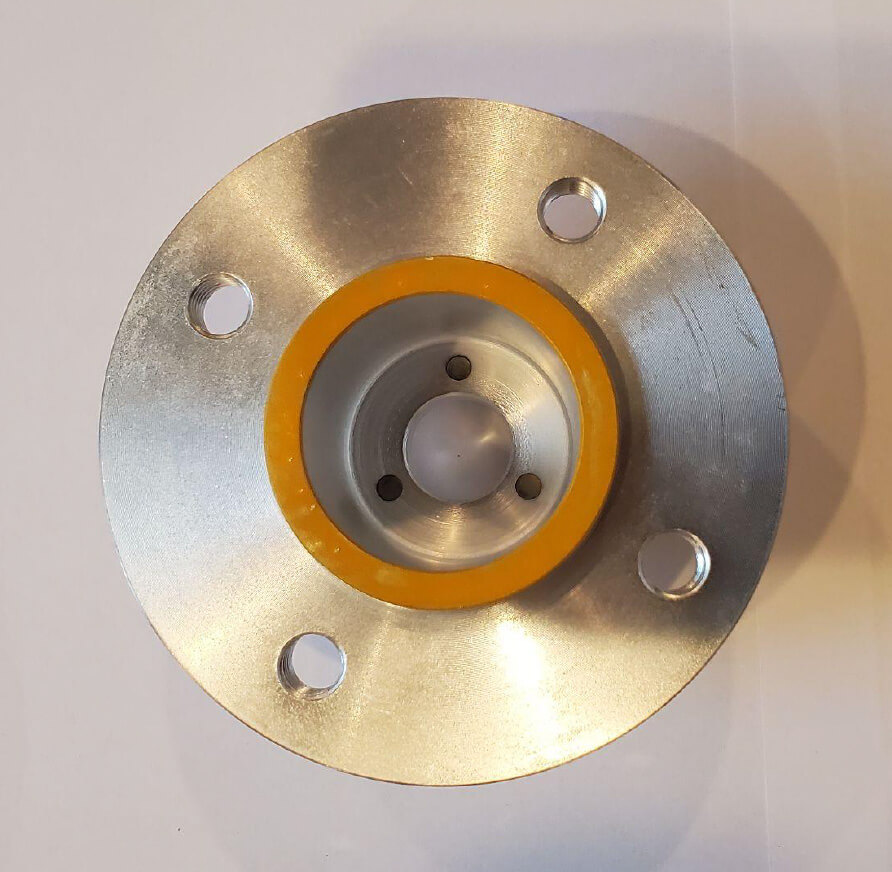
IMPORTANT NOTE : Butler System Crank Pulley Adapters for 2003-2020 6.0L & 4.8L engines are NOT compatible with 2021+ 6.6L engines. The 2021+ 6.6L Butler System Crank Pulley Adapter is identified by red sealant on the back side of the adapter and yellow paint on the front of the adapter.
Tools You Will Need:
- 15/16 ½" drive deep impact socket
- ½" drive 1" deep impact socket
- ½" drive torque wrench capable of 250lb/ft
- 10mm socket, ratchet, and extensions
- 13mm combination wrench
- 17mm socket and ratchet
- Electric or battery operated drill
- 2lb. dead blow mallet
- Anti-seize compound
NOTE: If new parts and/or hardware are supplied to you with these instructions, you must replace all the old items with the new ones supplied. New parts or hardware items may have been updated or improved upon without visible differences. Failure to install all new items may result in less than optimum performance and/or serious damages to your Butler System and/or vehicle.
Use only the drill bit(s) provided to perform this procedure. Use of drill bits other than those provided, may result in improper tolerances between Butler System and vehicle engine components. This may lead to less than optimum performance and/or serious damages to your Butler System and/or vehicle.
If this procedure is being performed on an engine that is out of the vehicle, some procedures may not apply.
Please call the Butler Corporation Service Dept. at 1-800-535-5025 before beginning this procedure if you are unsure of what to do or if you have any questions.
Drilling Crankshaft:
1.Disconnect negative battery cable.
2.Remove starter motor, following factory procedures.
3.Install Kent-Moore Crankshaft Lock Tool J-42386-A
4.Follow factory procedures to remove the following components to gain access to the crankshaft damper/pulley assembly:
- Air Cleaner and Snorkel
- Coolant overflow reservoir
- Upper fan shroud
- Radiator fan and spacer assembly
5.Remove factory crankshaft damper bolt & discard.
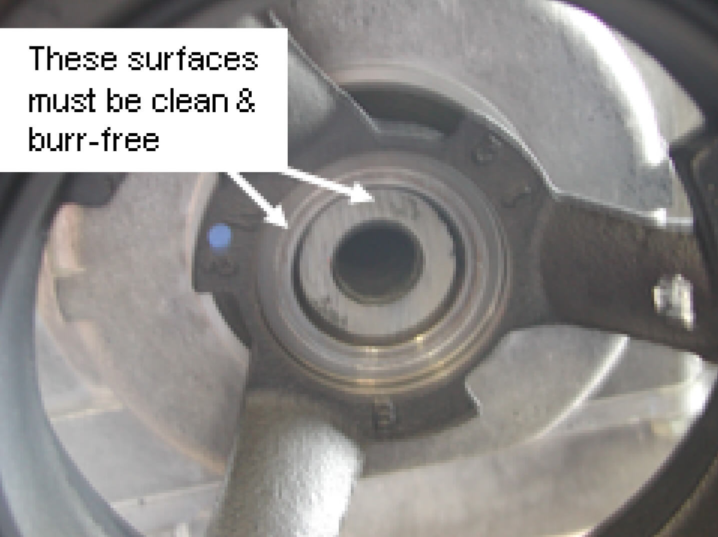
6.Thoroughly clean inner surfaces of crank snout and dampener.
- Caution: These surfaces must be very clean. If dirt or surface irregularities exist, the crank jig will not seat properly, resulting in improperly drilled holes. (below)
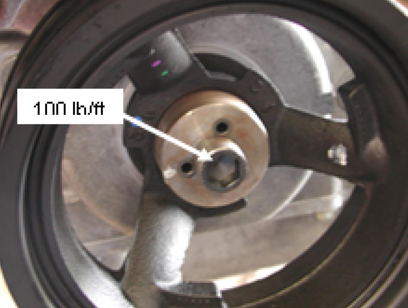
7.Position stepped side of Crank Drill Jig into the bore of the dampener until sealed. Install Crank Drill Jig Bolt and tighten by hand. Be sure to position the crank drill jig to avoid drilling into existing holes or keyways when applicable.
8.Torque Crank Drill Jig Bolt to 100 lb-ft. (below)
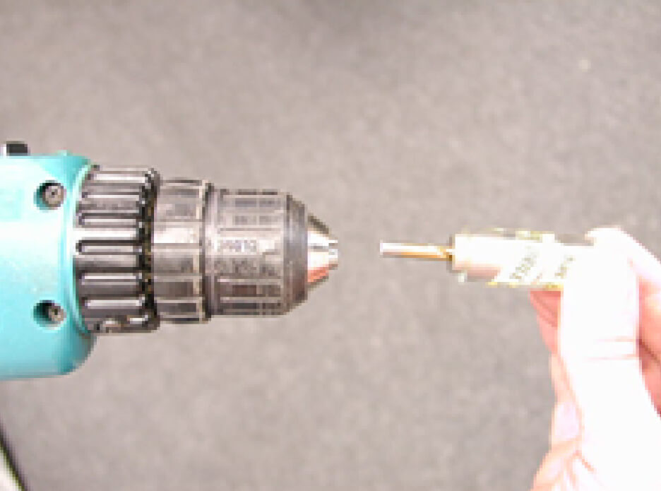
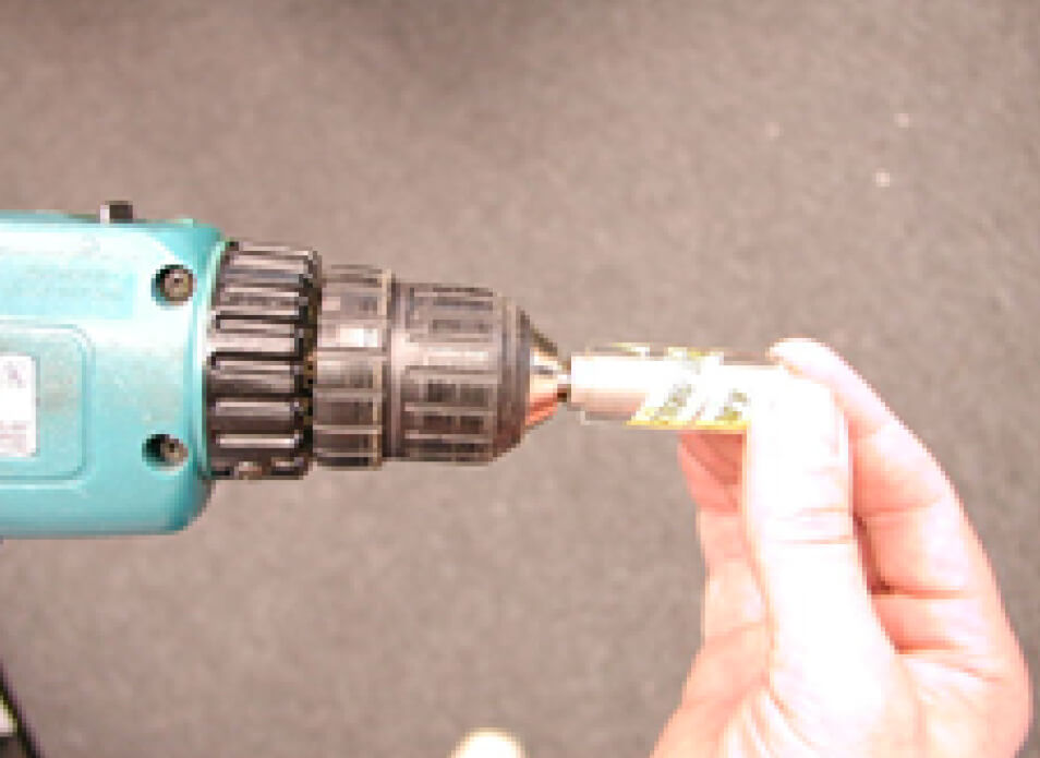
9.Place the 3/16" drill bit on the end of the drill depth gauge and confirm it is seated at the bottom of the gauge. (below left)
10.While holding the drill gauge and 3/16" drill bit upright so it remains seated in the gauge, place the drill chuck over the end of the 3/16" drill bit and tighten the drill bit in the drill chuck (below right)
11. Position drill bit in one of the holes in the Crank Drill Jig.
- DO NOT loosen or reposition the Crank Drill Jig once you have started drilling.
- Make sure the Crank Drill Jig does not move or rotate relative to the crankshaft.
- Pull drill back once or twice while drilling to allow shavings to discharge from the hole.
- DO NOT use any lubricant.
- DO NOT use a high speed air operated drill.
- Make sure the jaws of the drill DO NOT come in contact with the side of the Crank Drill Jig Bolt.
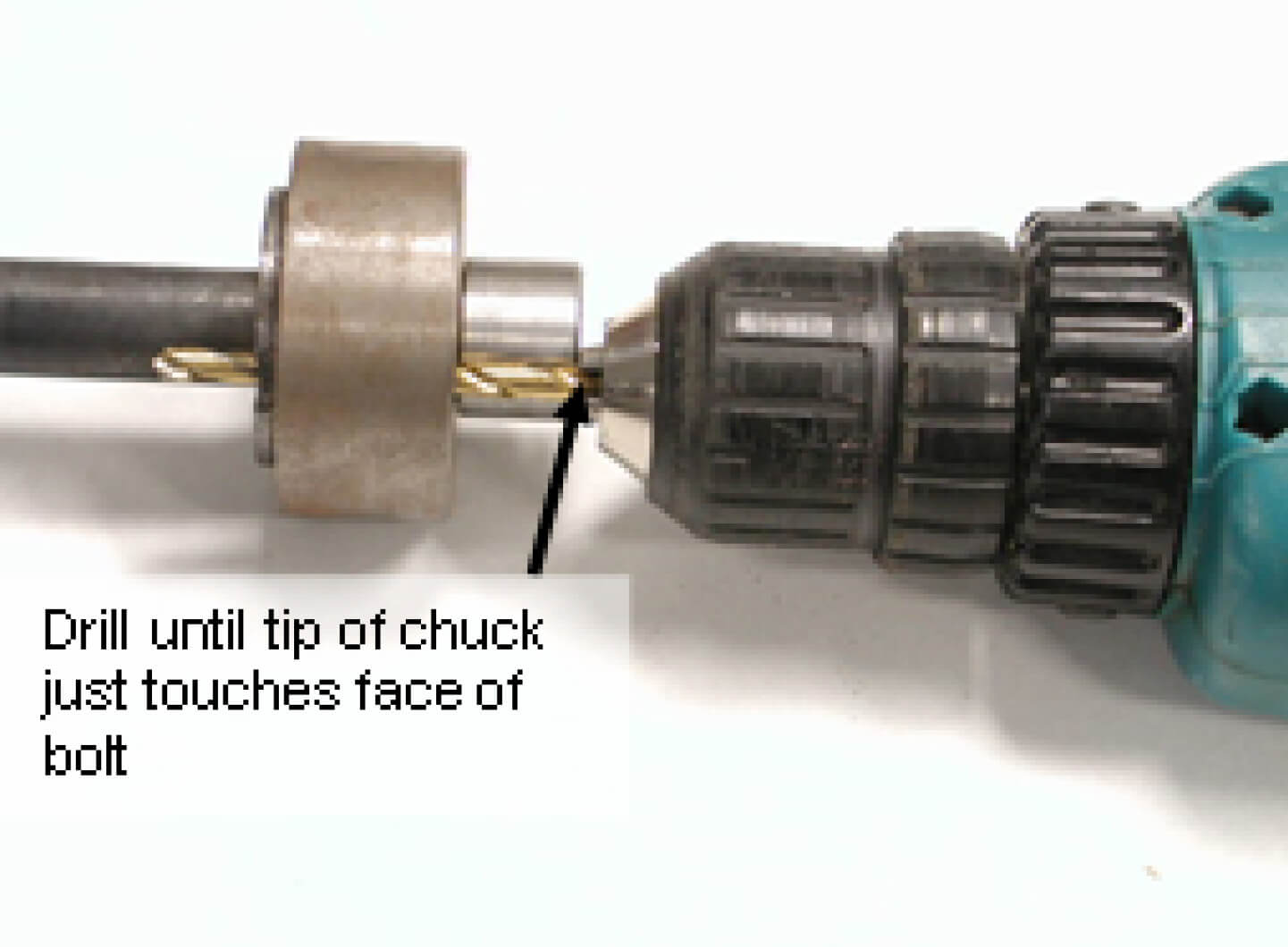
12. Drill Hole until jaws of drill just touch face of Crank Drill Jig Bolt. (shown below)
13. Without moving the Crank Drill Jig, repeat the drilling procedure for the remaining two holes in the Crank Drill Jig.
14. Recheck drill bit depth in drill chuck using Drill Depth Guide. If the drill has not moved, proceed to the next step. If the 3/16" drill bit has slipped in the drill chuck, use the Drill Depth Guide to reset bit depth and redrill all three holes to insure they are all at the proper depth.
15. When all three holes are completely drilled, loosen the Crank Drill Jig Bolt and remove the Crank Drill Jig.
16. Blow off the front of the crankshaft with compressed air.
17. Remove drill bit from drill and install the Chamfering Bit.
18. One at a time, align the Chamfering Bit with each drilled hole and lightly chamfer all three holes to remove any burrs.
19. Once again, blow debris off the front of the crankshaft with compressed air.
20. Visually inspect all three holes for burrs, and inspect the front of the crankshaft for any remaining debris, wipe clean if needed. Once the holes are confirmed to be drilled properly and the face of the crankshaft is clean, the Butler System Crank Pulley Adapter may be installed.
Installing the Butler System Crank Pulley Adapter:
- Thoroughly clean inner surfaces of the engine's crankshaft and clean the damper/pulley to ensure that there is no remaining dirt or debris.
- Insert Crank Guide Bolt into crankshaft and hand tighten. (below)
- Slide the Butler System Crank Pulley Adapter over the Crank Guide Bolt. While pushing against the Butler System Crank Pulley Adapter, holding it against the face of the crankshaft, rotate the Butler System Crank Pulley Adapter until the guide pins engage the 3 previously drilled holes in the crankshaft. (below)
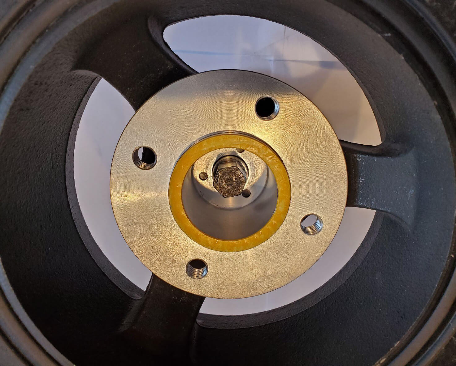
IMPORTANT: Pins on the Butler System Crank Pulley Adapter MUST ENGAGE HOLES in the face of the crankshaft before proceeding to the next step. Damage will occur if final torque is attempted without proper alignment.
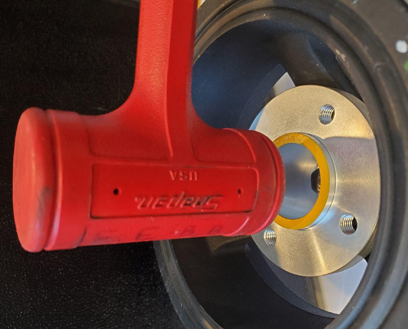
4. Using 2 lb. dead blow mallet, gently but firmly tap the collar at the front of the adapter, hitting flush in the center so as to seat the adapter properly in the crankshaft and damper. (below)
5. Carefully remove the Crank Guide Bolt.
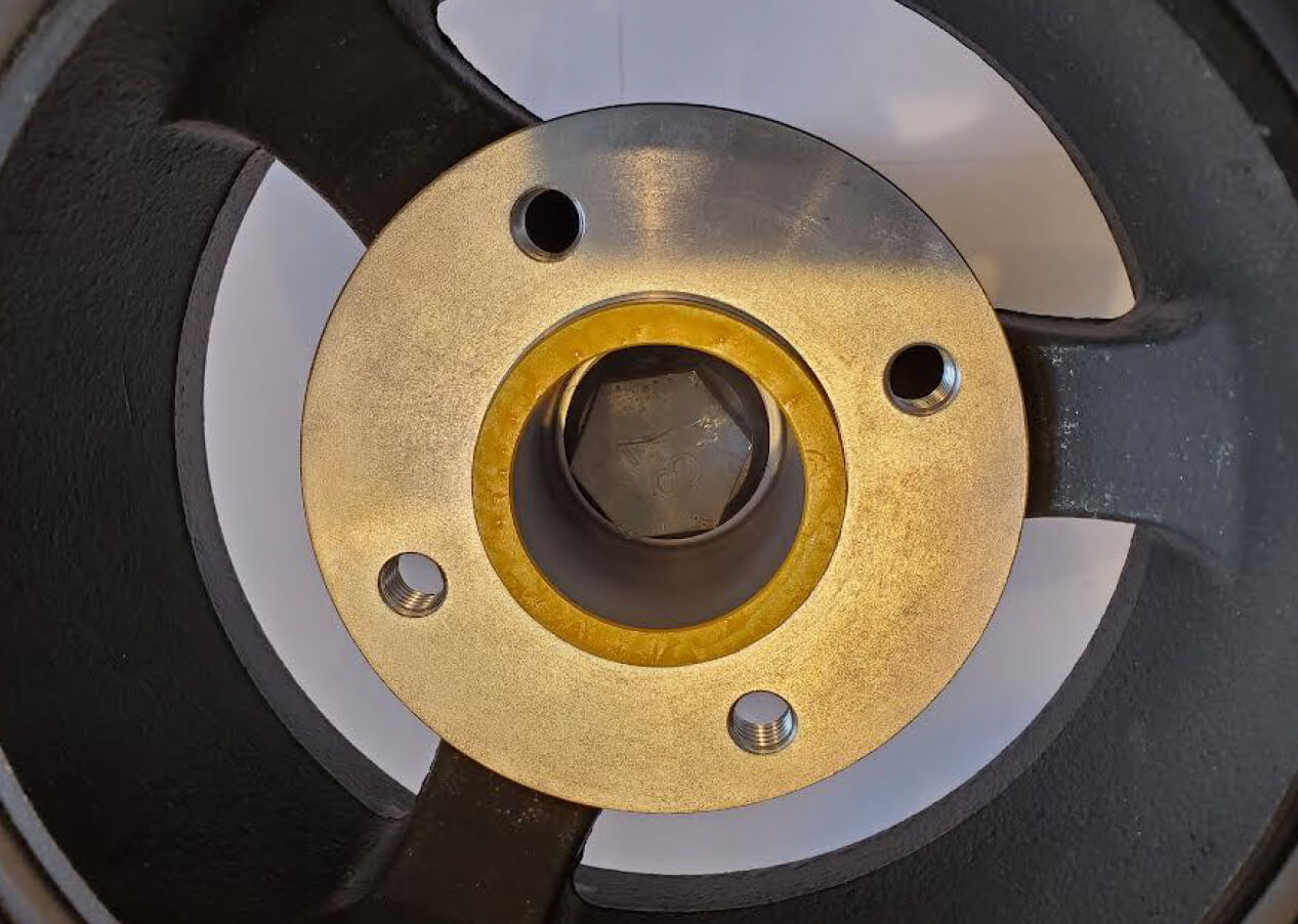
6. Insert the Crank Bolt, with thread sealant already applied, through the Butler System Crank Pulley Adapter and thread bolt into crankshaft by hand until the Crank Bolt becomes snug. (Below)
7. Set torque wrench to 240 lb-ft and tighten the Crank Bolt.
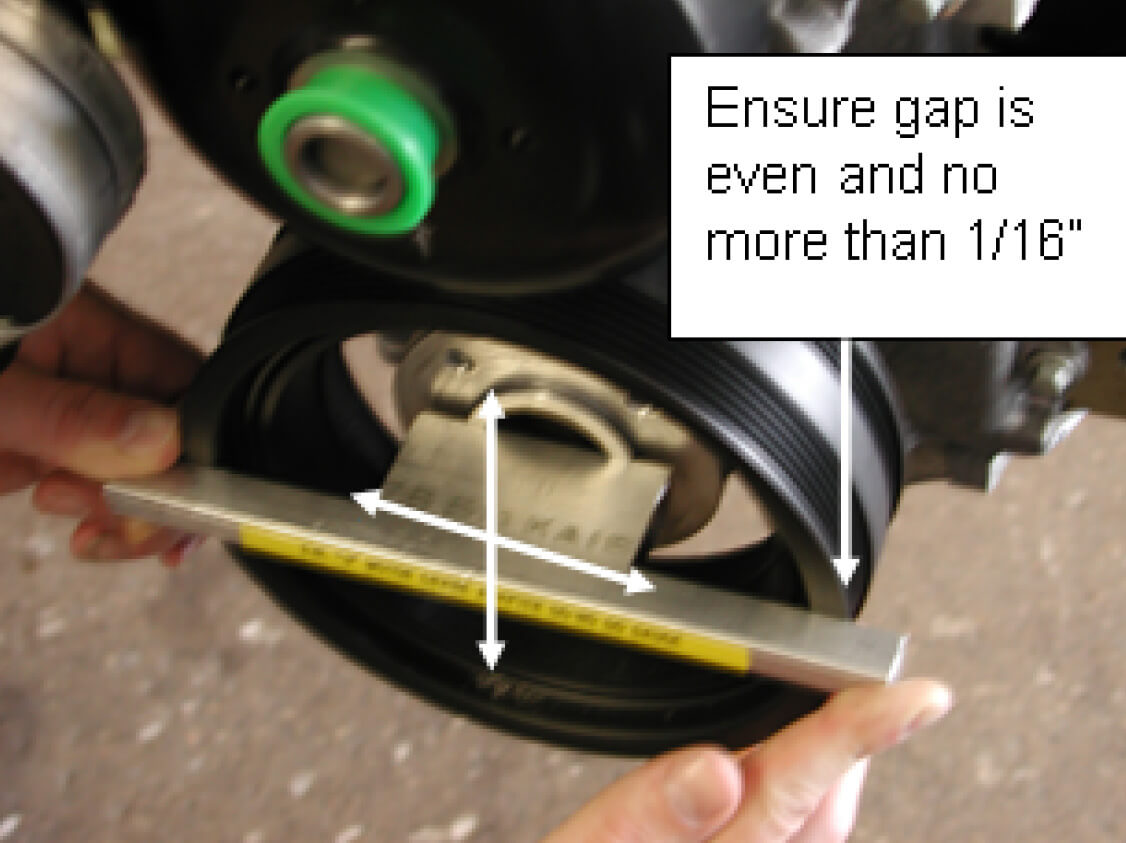
8. Place the Alignment Gauge against the face of the engine’s damper/pulley horizontally and vertically. Inspect the distance between the alignment gauge and the outer ring of the factory damper/pulley. (see below) If the distance between the alignment gauge and outer ring of the engine’s damper/pulley appears to be uneven, it means something is preventing the Butler System Crank Pulley Adapter from seating properly. If this occurs, remove the adapter, and inspect for obstructions or burrs. Once corrected, reinstall the Butler System Crank Pulley Adapter, with a new Crank Bolt, by following the previous 7 steps.
9. You may now install the Butler System Crank Pulley, being sure to follow the Butler System Crankshaft Pulley Installation & Replacement Procedure.
Butler System Crankshaft Pulley Installation & Replacement Procedure
It is important before starting this or any other procedure, that you or anyone who operates, works with, maintains, services or repairs the Butler System and/or vehicle, be familiar with its operation and thoroughly read, understand and follow, in their entirety, all of the Warnings, Cautions, and Notices described in your Butler System and vehicle Owners’ Manuals.
Carefully read and understand the complete list of instructions before proceeding.
Purpose: Install, or replace, and adjust, the Butler System Crankshaft Pulley.
Applicable Models: 2003+ Chevrolet, GMC vans and cut-aways, and Isuzu NPR and NQR cab-over trucks with 4.8l, 6.0l, and 6.6l V8 Gas engines.
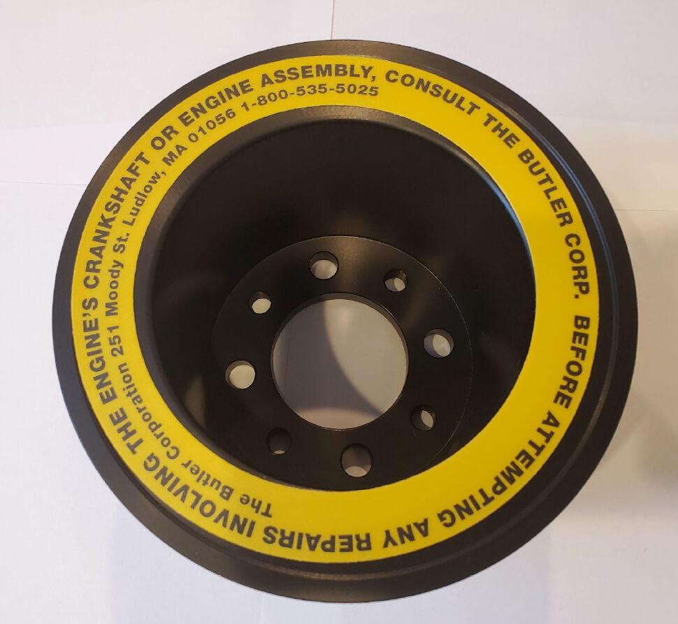
IMPORTANT: Use only a Butler System Crank Pulley with a YELLOW label. Pulleys identified with a YELLOW label are adjustable and require the following procedure to complete the proper installation. Failure to properly adjust (align) the pulley may result in engine vibration and possible damage to the vehicle and/or Butler System.
Parts to be Installed:
- Butler System Crankshaft Pulley with YELLOW label (shown below)
Special Tools Required:
- Magnetic mount travel dial indicator (shown below)
- ½" drive long handle ratchet
- ½" drive 3" extension
- 1" socket
- 2lb. dead blow mallet
- Torque wrench
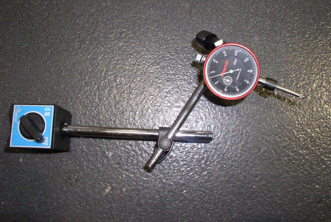
Magnetic mount travel dial indicator can be borrowed from The Butler Corporation upon request.
Removal Procedure:
- Disconnect the negative battery cable.
- Remove the coolant reservoir.
- Remove the air cleaner assembly.
- Remove the upper fan shroud.
- Remove the fan clutch assembly.
- Remove the two Butler System V belts.
- Remove (4) 9/16" bolts from Butler pulley.
- Remove Butler pulley. (may require light tapping with dead blow mallet)
Installation Procedure:
- Install the new Butler System Crankshaft Pulley (with YELLOW label) using four 9/16" bolts with flat and lock washers. Hand tighten only.
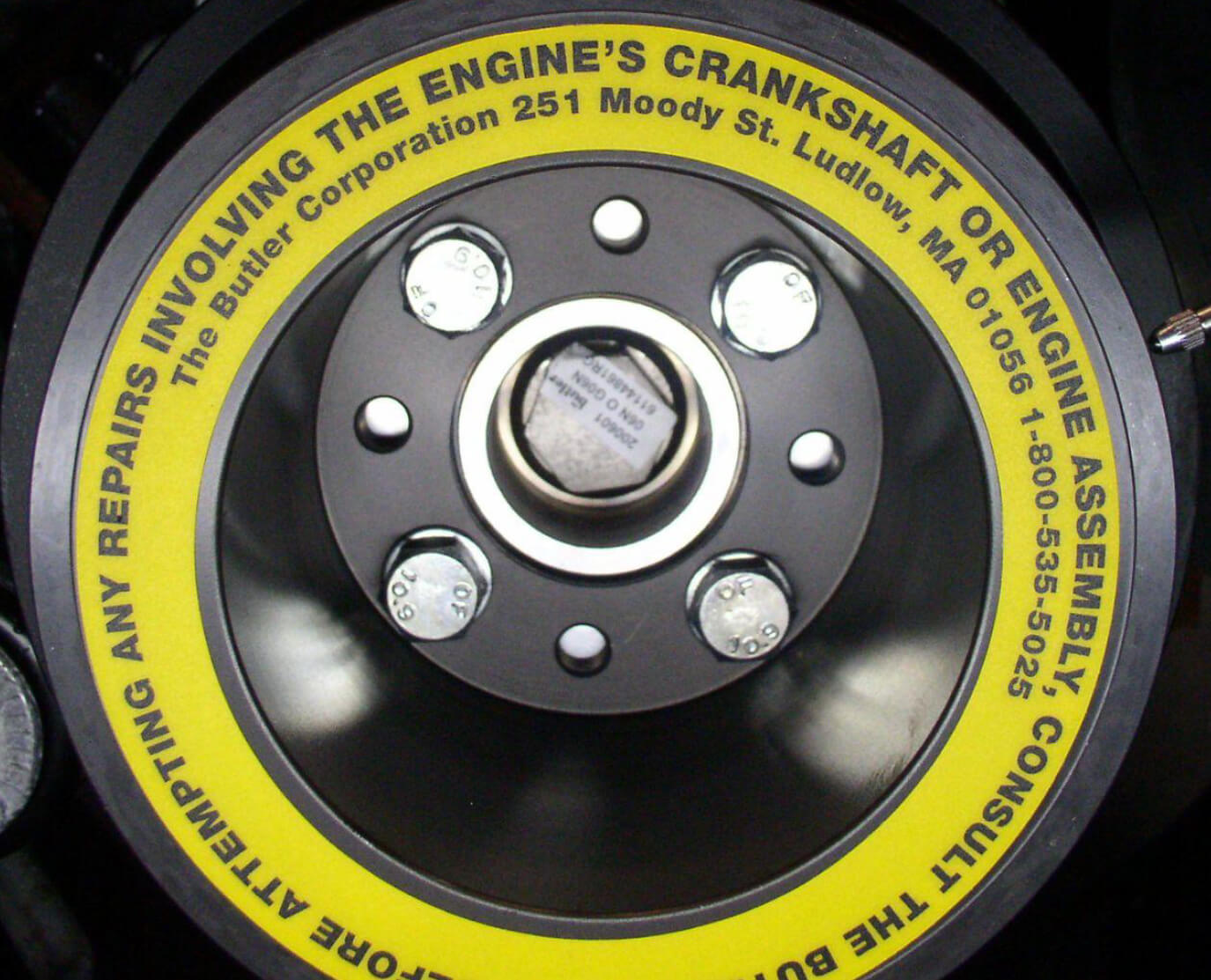
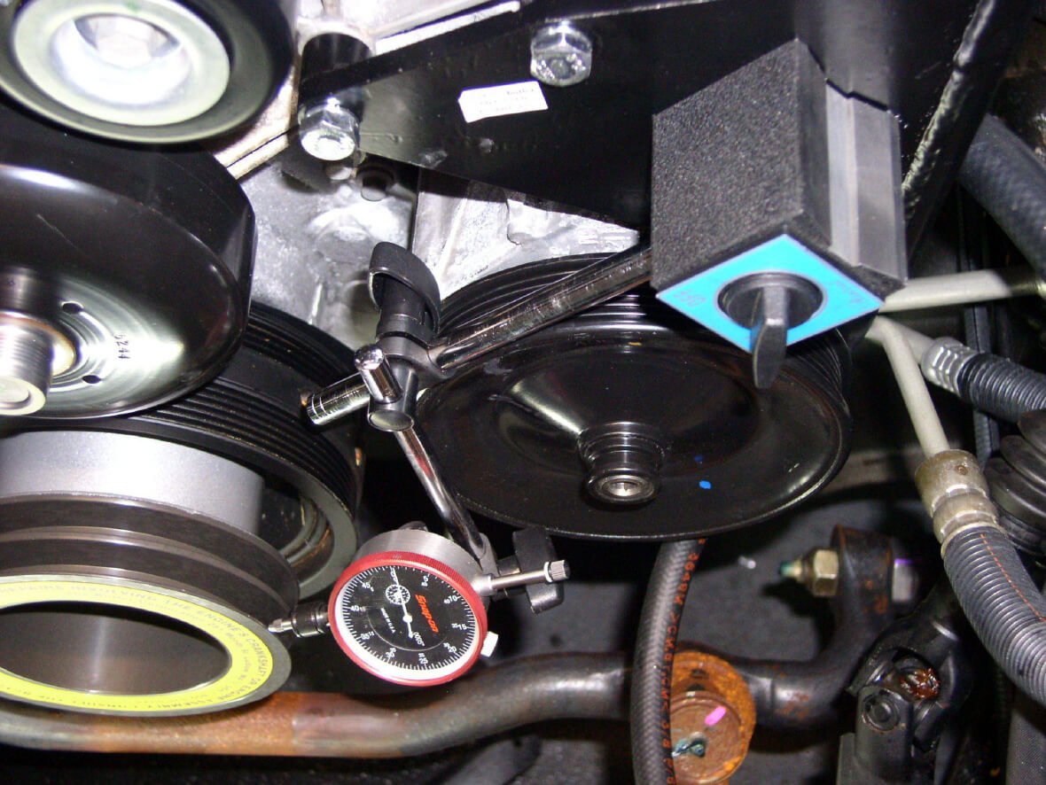
2. Mount magnetic dial indicator to suitable position. (Suggested dial indicator position for 2003-2020 6.0L & 4.8L V8 engines shown below.)
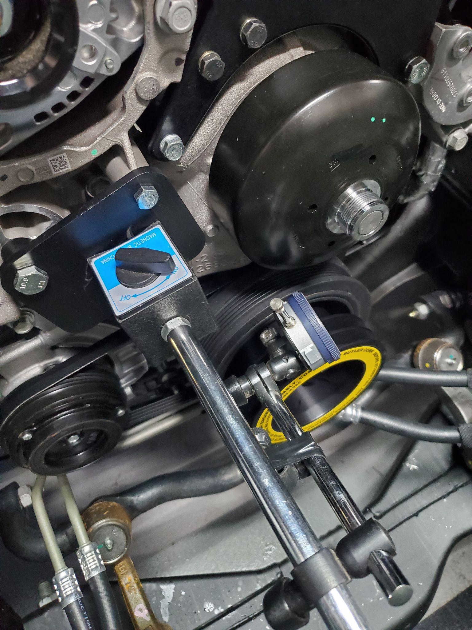
2a. 2021 and newer vehicles with 4.3L V6 & 6.6L V8 engines must use the dial indicator mounting plate available to rent in our crankshaft drill kits and dial indicator kits.(Suggested dial indicator mounting position shown below.)
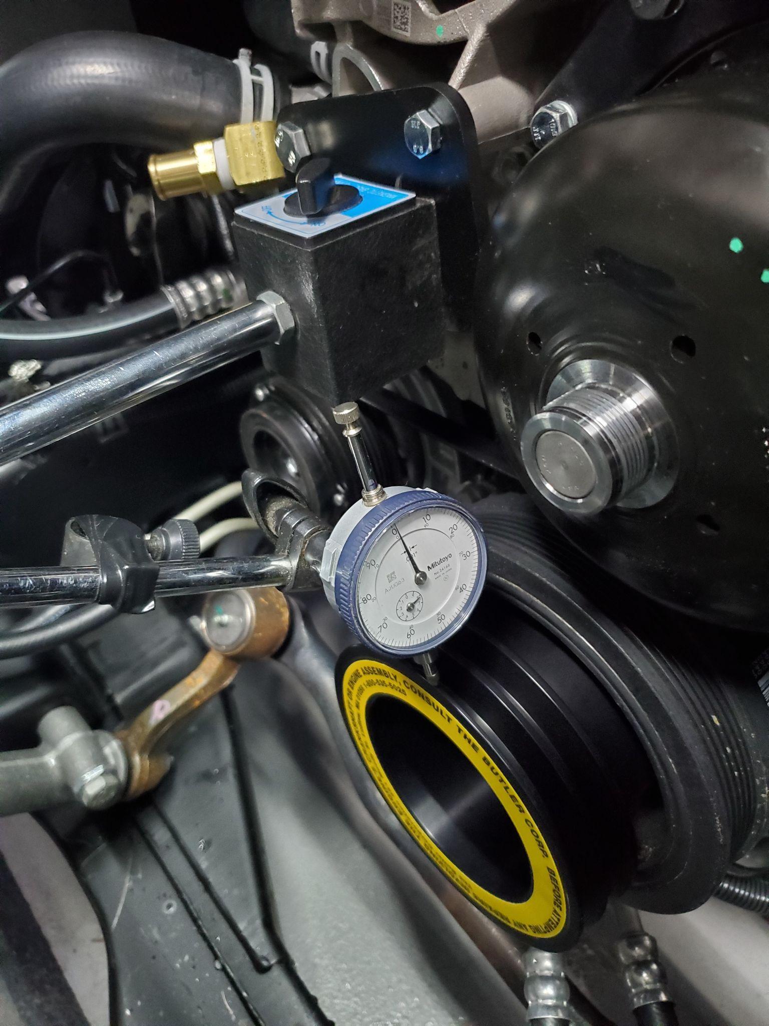
3. Dial indicator reading should be taken at the front ring of the Butler pulley.
4. Using ½" drive ratchet, 3" extension and 1" socket rotate the engine crankshaft clockwise one complete revolution.
5. Note the highest and lowest reading of the dial indicator. Subtract the lowest reading from the highest reading to determine the total dial indicator movement.
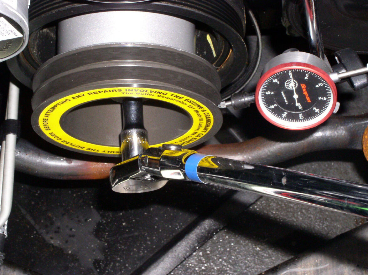
6. Continue rotating engine crankshaft clockwise until the lowest point on the pulley is shown on the dial indicator.
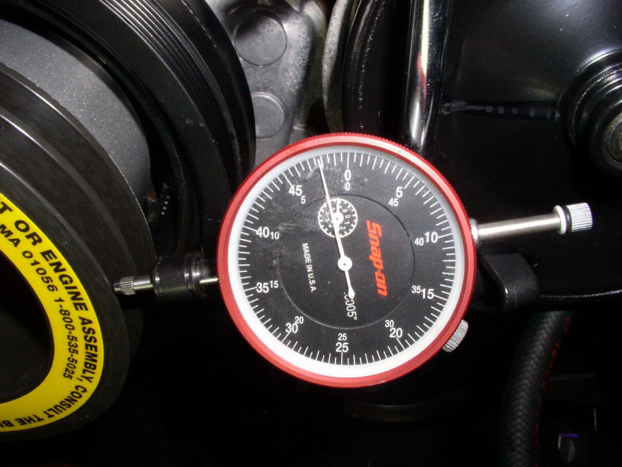
7. Gently tap the pulley towards the dial indicator moving the pulley 50% of total movement noted above (line 5).
8. Example: if total movement noted was .020in you need to tap pulley towards center .010in
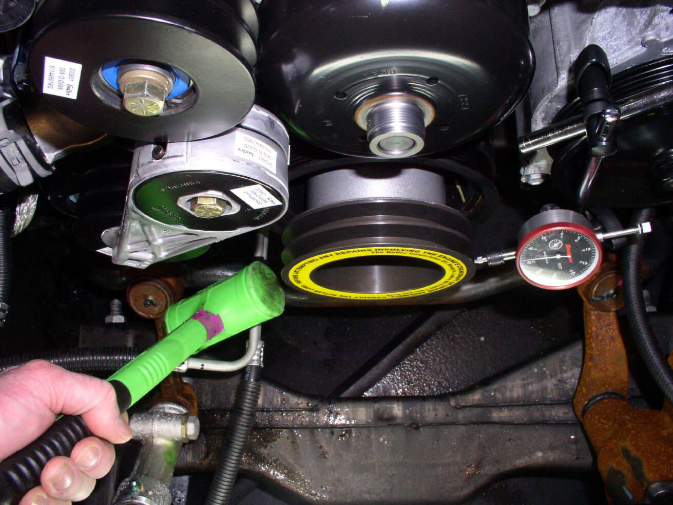
9. Rotate engine crankshaft clockwise again noting total dial indicator movement. Total dial indicator movement should be less than .010in, if not repeat steps 3 through 5.
10. Tighten the four pulley bolts to 37lb-ft.
11. Rotate engine crankshaft clockwise again. Total dial indicator movement should remain less than .010.
12. Remove the dial indicator.
13. Install (2) new Butler V belts.
14. Install fan clutch assembly and torque to 70lb-ft.
15. Install upper fan shroud.
16. Install air cleaner.
17. Install coolant reservoir.
18. Connect negative battery cable.
19. Start engine and inspect for any abnormal engine or Butler System Driveshaft vibrations.
If you have any questions, please call the Butler Corporation Service Department at (800)535-5025.
Butler System Crankshaft Pulley Installation & Replacement 20211209
Warranty Coverage
See Warranty Booklet for complete coverage details and limitations.







About Us
The Butler Corporation is a family-owned American business, providing factory direct sales, service and support to thousands of cleaning and restoration professionals in all fifty states, as well as, Canada, Bermuda, Cayman Islands, Puerto Rico, St. Maarten and various U.S. government agencies worldwide.
"The Butler System is especially appreciated by customers who work in extreme conditions, operate their business in remote locations or where dependable local service is not available."
When you invest in a Butler System you do so knowing with confidence that you will always receive factory direct service and support.